EN
EN RU
RU ES
ES FR
FR AR
AR IND
IND
Accurate Empowerment for Industrial Pipeline Installation: Quick Reference Table for Caliber, Flange and Installation Length of Blind Valves
This quick reference table for blind valve parameters is applicable to various industrial sectors such as metallurgy, chemical engineering, gas supply, and power generation. This table compiles all the commonly used parameters for the diameter, flange size and installation length of blind plate valves.
This table is compiled in accordance with two national industry standards, JB/T81-94 and GB/T13927. This table unifies the common dimensions of mainstream blind valves such as manual, pneumatic, electric and ching-driven ones available on the market.
This reference table can solve many common problems at construction sites. This table can standardize the disordered parameters for pipe selection, prevent misalignment of pipe interface connections, and reduce the situation of installation rework. This table can provide a unified and standardized reference basis for pipeline design, on-site construction, project acceptance, and daily operation and maintenance.
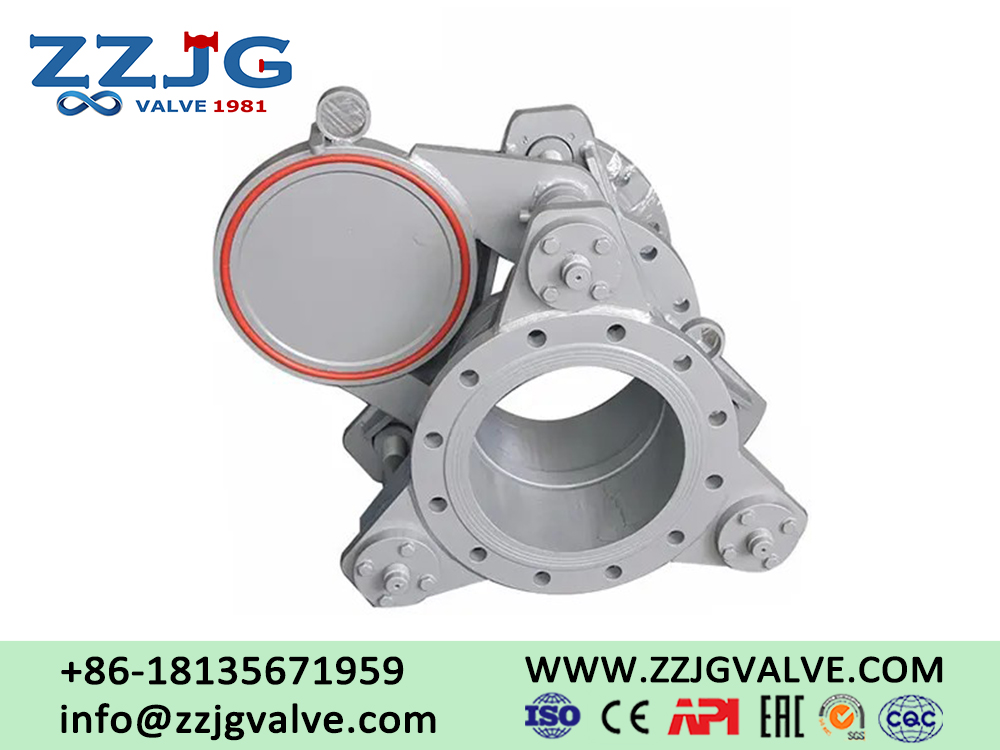
Blind valves are core safety devices in industrial pipelines. Industrial pipelines mainly transport flammable and high-risk fluid media such as natural gas and coal gas. Blind valves can isolate and block the medium in pipelines, ensuring the safety of pipeline operation.
-1.webp)
The alignment accuracy of flanges and the installation length accuracy of valves directly affect the sealing effect of pipelines and also directly determine the operational safety of the entire pipeline.
The parameter reference table released this time covers all the commonly used engineering specifications from DN250 to DN2000. This table mainly organizes three core parameters, namely valve diameter, flange size and equipment installation length. This table is compatible with most mainstream blind valve models on the market, has good versatility and strong on-site practicality.
This table distinguishes between two installation dimensions: short series and long series. All flange parameters comply with national industry standards. Staff can directly use this form to complete on-site centering calibration, size verification, equipment selection and other tasks.
This table can reduce the working time for parameter verification, avoid construction problems such as non-standard size mismatch, pipeline leakage, and abnormal equipment connection, and effectively improve the installation quality and usage safety of pipelines.
Quick Reference Table for Blind Valve Diameter, Flange Size and Installation Length Parameters (Industrial Standard Version, Unit: mm)
| Nominal Diameter DN | Flange Outer Diameter D(mm) | Bolt Circle Diameter D1(mm) | Flange Thickness b(mm) | Bolt hole specification n-Φd | Short Pattern L(mm) | Long Pattern L(mm) | |
| 250 | 375 | 335 | 14 | 12-Φ18 | - | 500 | |
| 300 | 440 | 395 | 16 | 12-Φ22 | - | 500 | |
| 350 | 490 | 445 | 16 | 12-Φ22 | 290 | 500 | |
| 400 | 540 | 495 | 16 | 16-Φ22 | 310 | - | |
| 450 | 595 | 550 | 20 | 16-Φ22 | 330 | - | |
| 600 | 755 | 705 | 26 | 20-Φ26 | 680 | - | |
| 700 | 860 | 810 | 26 | 24-Φ26 | 680 | 600 | |
| 800 | 975 | 920 | 26 | 24-Φ30 | 680 | 800 | |
| 1500 | 1675 | 1620 | 32 | 36-Φ30 | 830 | 850 | |
| 1600 | 1790 | 1730 | 32 | 40-Φ30 | 830 | 850 | |
| 1800 | 1990 | 1930 | 32 | 44-Φ30 | 900 | 1100 | |
| 2000 | 2190 | 2130 | 26 | 48-Φ30 | 1000 | - | |
Notes:
1. The parameters in this table follow the JB/T81-94 flange standard and GB/T13927 valve inspection standard, and are suitable for mainstream blind plate valve products of manual, pneumatic, electric and chain structures.
2. The installation length L of the table is divided into two specifications: short series and long series, which can be adapted to different pipe installation spacings and meet various on-site construction requirements.
3. The applicable medium of the equipment is natural gas, coal gas and various industrial flammable and high-risk fluids. The normal operating temperature of the equipment is ≤80℃.
Next: Introduction to Lined Plug Valve
1.webp)